Altazimuth mountings offer great engineering advantages, since stresses can come only along a single plane. They are also smaller for a given telescope. Note that tracking an object with an alt-az mount requires simultaneous smooth motion about both axes, and that the field of view on the sky rotates. Thus large telescopes with alt-az mounts were unthinkable until computer control came along. All really large telescope designs are set to use alt-az configurations: the MMT, 6-meter BTA, Kecks, VLT, Gemini, etc.
All altazimuth designs have a blind spot near the zenith, where the coordinate transformation from HA-declination to altitude-azimuth gives a tracking rate in one coordinate too high for accurate motion (typically over a zone a few degrees across). This is remedied for special applications in a so-called alt-alt scheme, an altazimuth pointed at the horizon. However, in engineering terms an alt-alt has all the problems of an equatorial and none of the advantages, so it is used only for such purposes as satellite tracking.
In all of these types, careful structural analysis can decrease the settling time; one wants a rather high resonant frequency to damp motion and wind shake.
Acquisition and guiding: we need to be able to point the telescope at a desired place in the sky. In increasing order of utility, we may use finder telescopes, setting circles, and shaft encoders on the mount. In asking for the coordinates to input for setting circles or encoders, we may need to account for precession, nutation, atmospheric refraction, and any misalignment of the telescope axes. This last is done with a pointing model, a mathematical transformation between ideal and actual telescope position. Arcsecond accuracy has been achieved in several cases. Often offsets from a visible to an invisible object are done, using a local x,y system where Δx = 15 Δ α cos δ in arcseconds, and Δ y = Δ δ .
We also need to guarantee accurate tracking during an observation (whose duration may be limited by, for example, differential atmospheric refraction across the field of view). One may do this visually, with a guide telescope or offset guider and crosshair eyepiece, or using an autoguider. These now usually use a separate TV camera or CCD, with a computer moving the telescope to keep reference stars at the same place. Such closed-loop systems can surpass 0.1-arcsecond accuracy, defeating error caused by atmospheric refraction, periodic drive error, or flexure by closing the loop between telescope motion and error sensing. Guide telescopes can be especially vulnerable to differential flexure at long focal lengths (where they are most useful). Note that many modern designs dispense with the complex gear-and-worm trains of older drives, since closed-loop guiding and encoders make direct-drive systems competitively accurate. Other guiding technologies exist, such as mechanically moving probes carrying photomultipliers and image dissectors, and the interferometric prism systems on HST.
One may alter the desired track rate from so-called sidereal rate, for moving targets or to trail a star deliberately through the field.
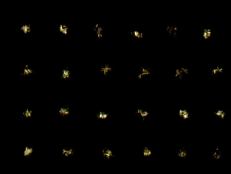
Atmospheric seeing: the instantaneous image of a point source is broken into many so-called speckles, due to the fluctuations in refractive index of the atmosphere on scales typically 10 cm. Speckles are caused by interference of the various cells of similar optical properties, which give regions typically 10 cm across of diffraction-limited performance - this size is the Fried parameter r0. In the Fourier domain, the amplitudes of various angular frequencies are the same, but their phases are rapidly scrambled. Speckles move on timescales of 0.03 second and faster, giving a long-exposure image that is their integrated envelope. This is often approximated as a Gaussian, but in fact has nearly exponential wings due to scattering (a shape known as a Moffatt profile). This blurring is generally known as astronomical seeing. There is an immense lore (some of it accurate) as to when and where the best seeing is encountered; it has become clear that in many places the seeing produced in or near the telescope is as bad as that in the free atmosphere. The montage below shows multiple images of a bright star using a webcam, with exposure times about 1/100 second and sampled about every second. This illustrates the highly variable nature of atmos[pheric seeing, as well as the characteristic speckle pattern when an image is frozen with a short enough exposure.
An exciting prospect opened up by recent (and newly declassified) technology is that of compensating for atmospheric wavefront disturbances in real time, using wavefront compensation or adaptive optics. If the real shape of the wavefront can be measured and compensating distortions introduced in the optical path fast enough, diffraction-limited imaging could be obtained. Measuring the distortion is possible with a reasonably bright star (and sometime using a laser scattered in the ionosphere). Correction uses a so-called rubber mirror. There has been considerable success in the near-IR, where the seeing is better and the timescale is longer. A sigificant improvement often comes from removing only the first components, the so-called tip-tilt or fast-guiding technique used on the HRCam at the CFHT on Mauna Kea. At a good site, a significant part of seeing is in image motion, which can be tracked with a nearby object and removed with a small wobbling mirror. One can also arrange to close the shutter during times of seeing worse than a specified level or take a series of short exposures and reject the worst ones ("lucky imaging"). There is great interest not only in adapting these technologies to new large telescopes, but in retrofitting existing telescopes. The gain for point sources in improving the seeing is phenomenal.
Last changes: 2/2011 © 2000-2011